FDM 3D Printing Tips for Designers. Tip 1 – CAD is King!
Posted on 2018/10/29

SHARE
Over the next few weeks, our Academy trainers are going to be sharing with you their top tips for FDM 3D printing. See below our very first top tip of the series, CAD is King!
Fused Deposition Modelling (FDM) is the most widely used and affordable process of 3D printing. It’s also one of the most effective additive manufacturing techniques for producing functional and workable parts. FDM printers operate by using a thermoplastic filament, which is heated to its melting point and then extruded, layer by layer, to create a three dimensional object.
Getting the most out of your FDM 3D printer is of critical importance. Failed parts or poor quality components lead to reprints of your components costing both time and money. FDM printing, like most manufacturing processes, does have some limitations and constraints on what can be printed, this article aims to address those and offer in condensed terms some key pointers on how to get the most out of your FDM printer, and also what steps you can take during the design stages.
It is important to note however, that additive manufacture is an iterative process much like design. In order to get the perfect part, it would be expected to do several prints- this ultimately depends on the application, and quality etc.
All about the CAD
The first aspect of consideration for your 3D oriented parts is the CAD file itself. Poorly designed CAD files with broken geometry or poor tolerances between parts will transcend through to a print. It’s important that the CAD model is first analysed in detail prior to a print- check for interference if applicable and ensure that design intent is maintained. By ensuring that your CAD model is accurate and integral, you can save yourself from a multitude of errors further down the 3D print workflow.
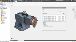
We would highly recommend both Autodesk Inventor and Autodesk Fusion 360 as CAD packages to consider. Both offer complete professional-grade digital prototyping tools needed to design, test, manufacture and manage your product.
See below: Interference fit check on an assembly in Autodesk Inventor
Check the .STL
Sticking with the software side of things, in order for your printer to accept a 3D CAD file, it will most probably have to be sent to another piece of 3D print pep software in the form of an. STL file. Most CAD packages can easily export a traditional solid CAD file into an. STL from the export options.
See below: Autodesk Netfabb showing errors in the .STL
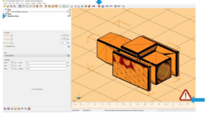
When doing this conversion from a solid model, it is not uncommon for. STL’s to become broken or have some geometry missing. Fortunately, most prep software can easily address these issues and run automatic repair scripts. If you are turning 3D scan data into an . STL this is something to be wary of.
Always remember the quality of the. STL directly affects the quality of the printed model!
Book now or just need More Info?
Any questions or book one of our training courses please phone 03332 075660 or email enquiries@3dprintacademy.co.uk