Designing for FDM Production Parts
Posted on 2019/05/20

SHARE
There are a different number of factors to consider when designing your production parts on an FDM printer. Here at the Academy, we understand these can get quite confusing so our technical trainers have got their heads together to put a best practice article together.
Build Orientation
This should be considered as a precursor to any detailed design, not just an FDM production part. Failure to consider build orientation early on will result in the need to compromise part quality and requirements at later stages of design.
Build orientation dictates the directional behaviour of design requirements, including: Mechanical properties, Aesthetics & surface finish, cost and time & accuracy. The ideal time for choosing build orientation is after the concept design is completed but before detailed design requirements are implemented.
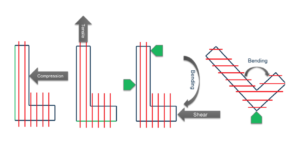
Mechanical Properties: Generally speaking, mechanical properties are best in the X-Y build plane and weaker across layers. See below picture of optimal build orientation for a given loading condition with respect to mechanical properties.
Aesthetics & Surface Finish: Aesthetics and surface finish are best when features are aligned vertically. You can do this minimising the angle between the vertical axis and a wall ensures that layer stacking is as concentric as possible.
Cost & Time: Build time is reduced by minimising Z build height and minimising the number of layers requiring both model and support material.
Accuracy: A feature will have the best accuracy if it’s outside mold line, is traced out on the X-Y build plane.
Self Supporting Features
FDM has the unique ability to produce certain geometric features without the use of support material. This enables you to have a fully enclosed lattice structure, fill patterns or hollow parts. Typically a overhang does not require support material if its walls or features do exist at a 45-degree angle or less from vertical.
Considerations for eliminating support material…
There are a number of reasons that a designer or a user of the 3D printer would want to remove support material within a design. It is one of the highest contributing factors in a parts cost, the predominant issue being part production time:
- In a parts build, support material and model material are deposited successively through independent nozzles
- During deposition, the inactive tip is kept at an idle state so that the material does not degrade or secrete from the tip on to the part.
- This process takes between 30 seconds to a minute, depending on the material. As a result of this, each layer that requires both model and support material adds a minimum of 30 seconds to the build time during which the machine is not producing a part.
Tolerance
As most of us know, the FDM process involves the deposition of a thermoplastic at elevated temperatures, therefore a parts tolerance will depend on it’s behaviour whilst shrinking. Thermal mass and part geometry, among other factors dictate how appropriate the default shrink factors are for matching actual part behaviour. A high level of confidence exists for any given geometry that a part tolerance will meet or exceed. The specifications are seen below:
Fortus 360/400mc™: ± 0.005 in. or ± 0.0015 in. (± 0.127 mm or ± 0.0015 mm), whichever is greater.
Fortus 900mc™/Stratasys F900™: ± 0.0035 in. or ± 0.0015 in. (± 0.089 mm or ± 0.0015 mm), whichever is greater.
Holes
The minimum hole size for an FDM part depends on the material used since different materials expand and shrink at different rates. All materials are capable of producing holes down to 0.0625 inch (1.6 mm). Re-designing holes as self-supporting diamonds or tear drops, will eliminate the need for support material regardless of the hole size, if the design requirements allow.
Minimum Feature Size
Minimum feature size is a function of slice thickness, tool-path width, and orientation. As a rule of thumb, the minimum feature size is 0.016 inch (0.4 mm). This is available on 0.005 inch (0.127 mm) slice thickness configurations. For features that approach or exceed the minimum suggested thickness, it is advisable to preprocess the part in the correct orientation to validate that the geometry can be filled sufficiently.
Text
The minimum suggested text size on the top or bottom build plane of an FDM model is a 16 point, boldface. Minimum suggested text size on vertical walls is 10 point, boldface. If vertical text is embossed inward, the supports for the text can usually be eliminated, because of the ability of FDM to bridge small gaps. In most cases, outward-protruding text can also be produced without support material, if the protrusion is less than .020 inch (0.51 mm).
Wall Thickness
The minimum wall thickness must be calculated relative to the build directions, rather than using a thickness value normal to the part surface. Minimum wall thickness in the Z direction is equal to the layer thickness. Remember that when approaching the minimum thickness, the as-built thickness will be rounded down to the nearest multiple of slice thickness. For example, a 0.007 inch (0.178 mm) horizontal wall produced with a 0.005 inch (0.127 mm) slice thickness will likely be rounded down to 0.005 inch (0.127 mm), with the remaining 0.002 inch (0.051 mm) being filtered off.
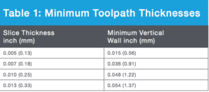
As a rule of thumb for those users who are not able to produce constant X-Y thickness thin-walled geometry, the following “safe” suggested minimum X-Y wall thicknesses are provided. These are 3x the minimum tool-path thickness for each slice thickness.
If you are still after more information on how to design your FDM Production parts, and are looking for some of our academy ‘insider knowledge’ then just pick up the phone and give us a call! Alternatively, tap in to our trainers brains and drop them a line: enquiries@3dprintacademy.co.uk
Book now or just need More Info?
Any questions or book one of our training courses please phone 03332 075660 or email enquiries@3dprintacademy.co.uk